 Sheet Metal Gusset Design Guidelines - DesaignHandbags
Metal Sheet Design Guides Metal Design Sheet Design Guide Design Guide Metal Sheet Introduction These basic guidelines for the manufacture of metal sheets include an important design considerations to help improve the manufacture of parts, improve cosmetic appearance, and reduce overall production time. Basic Principles Manufacture of metal sheet is the process of forming parts of a metal sheet when hitting, cutting, stamping and folding. 3D CAD files become machine code, which controls a machine to cut and form the leaves in the final part. The sheet metal parts are known for their durability, making them large for end-use applications (e.g. chassis). The pieces used for low-volume prototypes, and high-volume production runs are more profitable due to large initial configuration and material costs. Because the parts are formed from a single sheet of metal, the designs must maintain a uniform thickness. Be sure to follow the design requirements and tolerances to ensure that the pieces fall closer to the design intent and metal cutting sheets Basics Training Bending Bending is a process by which a force is applied to metal sheet that makes it fold in an angle and form the desired form. Benefits can be short or long depending on what design requires. The bending is made by a press brake machine that can be loaded automatically or manually. Pressure brakes are available in different sizes and lengths (20-200 tons) depending on the process requirements. The press brake contains a superior tool called the coup and the lower tool called the matrix between which the metal of the blade is placed. The blade is placed between the two and remains in place on the back. The curvature angle is determined by the depth that the blow forces the blade in death. This depth is controlled precisely to achieve the required curve. The standard tool is usually used for coup and death. The tool material includes, in order to increase strength, hardwood, low carbon steel, tool steel and carbide steel. The folding parts are supplied as flat patterns with bending information. Sometimes, the curvature positions are folded with curve mues, or these muscas can be cut to show the curves where to bend. Once the laser has cut the flat parts, they can be sent to fold. A press brake forms the flat pattern in the abnegada part. Critical dimensions The following are some terminology used in metal sheet. Designers must adhere to the machinery guidelines when designing to fold. The benefits can be characterized by these parameters. Some critical dimensions that should be considered when configuring the sheet metal in the CAD software are the thickness of the sheet, the k factor and the curvature radius. We must check that these factors are consistent with the tool that will be used in manufacturing. This guide offers important guidelines for good design practice. Bend Line... The straight line on the surface of the blade, on each side of the curve, which defines the end of the level flange and the beginning of the curve. Radio Bend – The distance from the axis of the curve to the inner surface of the material, between the lines of the curve. Bend Angle – The angle of the curve, measured between the tilted flange and its original position, or as the angle included between the perpendicular lines drawn from the curvature lines. Sometimes specified as the inner curve radius. The outer folded radius is equal to the inner fold radius plus the thickness of the blade. Neutral Axis – The location on the blade that is not stretched or compressed, and therefore remains at a constant length. K-factor – The location of the neutral axle in the material, calculated as the ratio of the distance of the neutral axle T, to the thickness of material t. Factor K depends on several factors (material, curved operation, curved angle, etc.) and is greater than 0.25, but cannot exceed 0.50. K factor = T/tBend subsidy – The length of the neutral axis between the curvature lines or the length of the curve arc. The margin of curves added to the lengths of the flange is equal to the total flat length. K-Factor The K factor is the relationship between the neutral axis to the thickness of the material. Importance of factor K in metal sheet design The K factor is used to calculate flat patterns because it is related to how much material is stretched during curvature. Therefore, it is important to have the correct value in the CAD software. The value of factor K should range from 0 – 0.5. To be more accurate, factor K can be calculated by taking the average of 3 samples of bent parts and plug the measurements of the allocation of curves, curve angle, material thickness and internal radius into the following formula: Here are some basic values of factor K. Use these as a guideline. Wall thickness The parts need to keep a uniform wall thickness in everything. Usually the capacities of 0.9mm – 20mm thick are capable of being manufactured from the sheet (3mm) but this tolerance depends mainly on the part. When considering the thickness of a plate, a single sheet with a punch (holes) is a good thumb rule. Some features such as countersinks are doable but counter-retro ferries and other machined features are difficult to produce as they require post machining. Bending Bend Radius The blade metal curvature brakes are used to fold the material into the desired geometry. The benefits that are on the same plane need to be designed in the same direction to avoid the orientation of the re part, to save both money and time. Maintaining consistent curve radius will also make the parts more profitable. The thick parts tend to be inaccurate to avoid them if possible. Small curves to large. Consistent Orientation Inconsistent Retreat When folding a piece of metal sheet, residual tensions in the material will cause the sheet to the beet slightly after the bent operation. Due to this elastic recovery, it is necessary to bend the blade a precise amount to reach the desired curve radius and curvature angle. The final curvature radius will be greater than the initially formed and the final curve angle will be smaller. The final curve angle ratio with the initial curve angle is defined as the springback factor, KS. The amount of springback depends on several factors, including material, curved operation, and initial curve angle and curvature radius. Dimensions: To prevent the parts from fractured or distorted, make sure to keep the inner curve radius at least equal to the thickness of the Angles material of the curve:A +/- The tolerance of 1 degree in all angles of curvature is generally acceptable in the industry. The length of the strip should be at least 4 times the thickness of the material. Thumb Rule It is recommended to use the same radius through all the curves, and the length of the flange should beat at least 4 times the thickness of the material. MinimumBend Radius, rMinimum curved radio requirements can vary depending on applications and materials. For aerospace and space applications, values can be higher. When the radio is less than recommended, this can cause material flow problems in soft material and fracture in hard material. In such cases, localized scotch or fracture may also occur. It is recommended that the minimum internal curvature radius should be at least 1 times thickness of material. Minimum Longitude of the staircase, bThis is the minimum length of the curve must be supported until the curve is complete, the flange must be long enough to reach the top of the death after it has been completely formed. Brake press operators should know the minimum lengths of the flange for their tools before trying curves that may not work and while it is possible to calculate the minimum flange that has a force load of Air Bend by hand certainly makes it more convenient. The thickness of the material, tThe thickness of the material is not proportional to the tonnage as the opening v. Duplicating the thickness does not mean duplicating the tonnage. Instead, the bending force is related to the thickness square. What this means is that if the thickness of the material is folded the required tonnage increases 4 folds. Work the length of the piece, L As the v that opens the required tonnage is directly related to the length of the workpiece. Duplicating the length of the work means duplicating the required tonnage. It should be noted that by folding short pieces, less than 3" in length, the required ton can be lower than that which is proportional to its length. Knowing this can prevent damage to a death. Air Force Bending Charge Air Force Bending is a graph showing the tonnage used to fold different thickness panels. It is useful for metal sheet designers, as it specifies the curvature radius and the tool to be used for different thicknesses. It is shown here for soft steel. Designers can use this as a guide when designing the minimum length of the possible flange with the tool for different V blocks as well as the curvature radius. The following graphics are based on the curvature guide of the Armed Air Force. Bend Relief When a curve is made near a edge the material can tear unless it is relieved of curvature. The Bend 1 shows a tear. The Bend 2 shows a rectangular relief cut in the part, the depth of the relief should be greater than the radius of the curve. The width of the relief should be the thickness of the material or greater. Bend reliefs are used where a curve extends on a edge. The needle is added to avoid tearing. The folded reliefs will not be deeper than the thickness of the material plus the curvature radius. Width HeightSlender height The height of the beetle curve must be at least twice the thickness of the sheet plus the curvature radiusH=2t + rIf the height of the curve is too small, this will result in deformation and low bending quality. Forming near the holes When a curve is made too close to a hole the hole can be deformed. Hole 1 shows a hole that has become teardrop in shape due to this problem. To save the cost of perforation or perforation in a secondary operation you can use the following formulas to calculate the required minimum distance: For a slot or hole D = 2t + rAs a thumb rule the distance from the outside of the material to the bottom of the cut should be equal to the minimum length of the brid as prescribed by the air curvature force diagramD = 2.5t + rWhen a pulsation is used, or laser cutting Minimum distance from the hose extruded to the hose of the partExtruding metal is one of the most extreme pressure applications in the press work and generates a lot of friction and heat. If an extruded hole is too close to the edge of the part, it can lead to deformation or tear of the metal. It is recommended that the minimum distance between holes extruded to the edge of the part should be at least three times the thickness of the sheet. Minimum distance between extruded holesThe distance between two extruded holes in metal sheet designs. If the extruded holes are too close can lead to metal deformation. It is recommended that the minimum distance between two extruded holes be six times the thickness of the metal sheet. Minimal hose diameter The hole diameter in the metal sheet part should not be very small, the small holes are created by drilling the operation and for the manufacture of small holes, small sizes are required. The small size of metal sheet hole requires a smaller-size drilling tool that can lead to breaking during operation. It is recommended that the diameter of the hole be equal or superior to the thickness of the metal of the blade. Laser cutting Laser cutting is a type of production that uses a laser to cut different metals. The laser has a high-energy beam that burns easily through the material. Laser cutting can be used in materials such as metal, aluminum, plastic, wood, rubber, etc. Lasers use numerical control programming (CNC) to determine the form and position of the cuts. Material thicknesses up to 20 mm can be cut with laser. There are advantages and disadvantages in laser use. CO2 lasers are more traditional, and can cut thicker materials but do not offer a cut as precise as fiber lasers. Fiber lasers can usually cut thinner materials and have cutting speeds much higher than CO2. Advantages and disadvantages The advantages of laser cutting on cutting mechanically include better placement, a reduction in the contamination of parts, a greater accuracy and a lesser possibility of covering as the area affected by heat is small. Some disadvantages are that laser cutting does not always cut well with some materials (e.g. not all aluminum) and is not always consistent. Despite the disadvantages laser cutting is highly efficient and cost-effective. General Tolerances If the customer has not provided a drawing sheet or specification, we will manufacture the model product to the specifications listed here. The sharp edges will be broken and disbursed by default. Critical edges that should be sharpened should be noted and specified in an impression. Material Restrictions Materials that are not suitable for laser cutting include mirror or reflective materials, Masonite boards, compounds containing PVC. Generally acceptable materials the following materials are suitable for laser cutting: metal, stainless steel, some aluminum thicknesses, wood and some plastics. Located hardening The local hardening takes place on the edges where the laser has cut. This hardening produces a durable and smooth edge without the need to finish after using the Laser CutterDistortionA heat-affected area (HAZ) occurs during laser cutting. In carbon steel, the greater the hardness, the greater the HAZ. The distortion of laser processing is the result of the sudden increase in the temperature of the material near the cutting area. The distortion is also created by the rapid solidification of the cutting area. In addition, the distortion can also be attributed to the rapid solidification of the remaining material on the sides of the court. KerfDuring the cutting of a part of the material burns when the laser is cut, leaving a small gap. This 'gap' is known as laser kerf and goes from 0.08 – 0.45mm depending on the type of material, thickness and other conditional factors. A minimum distance of 1-2 mm between the parts needs to be left to avoid accidental crossing. It is also recommended to keep the 2-5mm pieces away from the edge of the material because some leaves are being cut or slightly off in their size. One should always cut parts at the limit of the size of the leaf and not use the edges of the leaf as a border. Tolerances Wall Thickness Wall Thickness Because Sheet Metal parts are manufactured from a single sheet of metal, the part should keep a uniform thickness of the wall. Metal sheet parts can be manufactured with a minimum of 0.9 mm to 20 mm thick. Hole Diameter Hole Diameter When designing laser cutting parts one should not make holes smaller than the thickness of the material. BendsBends on metal sheet are made with metal sheet brakes. Tolerance +/- 1 degree at all angles of curvature. Other standard curve radios available, some of which will add additional cost to your part, include:0.9mm – 1.2mm1.8mm – 2.4mm3.8mm – 5.0mm7.5mm – 10mm15mm – 20mmCurlsCurl FeaturesThe metal of spreadsheet is the process of adding a hollow roll, circular to the edge of the blade. The curled edge provides strength to the edge and makes it safe for handling. The curls are used more often to remove a sharp edge and make it safe for handling. It is recommended that: The outer radius of a curl should not be smaller than 2 times the thickness of the material. A hole size should be at least the radius of the thickness of curling more the material thickness of the rizar feature. A curve should be at least the radius of the rim more 6 times the thickness of the material of the characteristic of the rizoCountersink HolesMachined and formed the contrasinks are possible after cutting. Machine counter sinks are created with a drill press while the trained counter sinks are created with press tools. The depths of the counter-synchronization should not exceed 0.6mm the thickness of the material. Countersink Tolerances Countersink Tolerances:Both machined and formed counters are available-conical holes cut into a manufactured object that allows inserting a screw, nail or screw with the surface. We recommend the main diameters of the contrasinks are between 2.3mm and 12.7mm using one of the following standard angles: 82°, 90°, 100° and 120°. Tolerance for the main diameter of formed counterweight is +/- 0.254mm. Brake dimensions The distance between the countersink centers should be maintained at 8 times the thickness of the material The distance between the curve line and the counterweight center must be kept at least 3 times the thickness of the material and 4 times the thickness of the material of a border. Hems: The principle of hemmingHems are folds at the end of a part to create a rounded edge. There are several methods to produce plateametal flattening The grip process is usually done in two steps: sharp-angle is thinning the envelope curve. A high compaction pressure is required for the slimming process. The process develops a great axial force. This force affects the material longitudinally of the machine. Hem Characteristics GuidesOpen and closed heels can be formed as needed. The tolerance of a helm depends on the radius, the thickness of material and the characteristics close to the helm. The inner minimum diameter equals the thickness of the material and the return length of the rudder is 4 times the thickness. Closed heels are folds at the end of a part to create a rounded edge. The tolerance of a helm depends on the radius, the thickness of the material and the characteristics close to the helm. It is recommended that the minimum inner diameter equals the thickness of the material, and the return length of the rudder is 6 times the thickness of the material. The grip is nothing but to bend the metal itself. In metal sheets are used to create metal sheets to harden edges and create a safe edge to touch. The edges are used more often to remove a sharp edge without treating and making it safe for handling. The edges are commonly used to hide imperfections and provide a generally safer edge to handle. A combination of two rings can create strong joints, narrow with a small or minimum fasting. The edges can even be used to strategically double the thickness of the metal in areas of a part that may require additional support. It is recommended that: For tear drop bells, the inner diameter should be equal to the thickness of the material. For the open hem the curve will lose its roundness when the inner diameter is greater than the thickness of metal sheet. For the curves, the minimum distance between the inner edge of the curve and the exterior of the hem must be 5 times the thickness of the material plus the radius of curves plus the radius of hem. Hole Slots: Dimensions Keep the diameters of the hole and the slot at least as large as the thickness of the material. The higher strength materials require larger diameters. ClearancesHoles and slots can be deformed when placed near a curve. The minimum distance to be placed from a curve depends on the thickness of the material, the radius of curves and its diameter. Be sure to place holes away from the curves at a distance of at least 2.5 times the thickness of the material plus the curve radius. The slots must be placed 4 times the thickness of the material plus the curve radius of distance from the curve. Make sure to place holes and slots at least 2 times the thickness of the material away from a edge to avoid a "bulging" effect. The holes should be placed at least 6 times the thickness of the material. CleaningsNights & Tabs FeaturesThe thighs must be at least the thickness of the material, which is greater, and can not be more than 5 times its width. The tabs should be at least twice the thickness of the material or 3.2 mm, which is greater, and cannot be more than 5 times its width. Torches Annotating is a drag operation that removes a section from the outer edge of the strip or part of metal. In case the distance between the mosses to fold is very small, then the distortion of metal sheet can take place. To avoid such conditioning it should be placed at appropriate distance from the curve with respect to the thickness of the sheet. The notching is a low-cost process, especially for its low tool costs with a small range of standard punches. Clearances Clearances Muescas must be at least 3,75 mm away from each other. For the curves, the nuts should be at least 3 times the thickness of the material plus the bend radius. The tabs must have a minimum distance between themselves of 1mm or the thickness of the material, which is greater. Recommendations for feeding notch:The width of notch should not be narrower than 1.5 * t.The length of the notches can be up to 5 * t. The recommended corner radius for the muscas should be 0.5 * t. Muescas should be at least the thickness of the material or 0.04", which is greater, and can not be more than 5 times its width. The tabs should be at least 2 times the thickness of the material or 0.126", which is greater, and cannot be more than 5 times its width. Features Corner filters Fill or round the corners of the sheet is made inordinate to provide a smooth finish. Statues eliminate sharpeners by facilitating the management and prevention of cuts and scratches. A steak is usually designed to be 1⁄2 the thickness of the material and the filling makes the parts more profitable. Relief cutsThe relief cuts help the parties approach the design intent to avoid the "outstandings" and tear the curves. Overhangs become more prominent for thicker parts with a smaller curve radius, and can even be as large as 1⁄2 the thickness of the material. The tearing can occur when the curves are made near a edge. Relief cuts DimensionsThe relief cuts for curves should be at least the thickness of a material in the width, and should be longer than the curvature radius. Dimensions Copyright © 2021 Geomiq. All rights reserved. Registration number. 10321594. VAT Nr.GB 258421205. We are using cookies to give you the best experience on our website. You can know more about which cookies we are using or turning them off in the settings. This website uses cookies to provide you with the best possible user experience. Cookies information is stored in your browser and performs functions such as recognizing you when you return to our website and helping our team understand which sections of the website you find most interesting and useful. Strictly necessary cookies must be enabled at all times so that we can save your preferences for the configuration of cookies. If you disable this cookie, we cannot save your preferences. This means that every time you visit this website you will need to enable or deactivate cookies again. This website uses Google Analytics to collect anonymous information such as the number of visitors to the site, and the most popular pages. Keeping this activated cookie helps us improve our website. Please activate the cookies strictly necessary first so we can save your preferences! This site uses the Lucky Orange analysis system to help improve customer usability and experience. Lucky Orange can record mouse clicks, mouse movements and scrolling activity. Fort Orange may register pulsation information that you voluntarily enter this website. Lucky Orange doesn't track this activity anywhere that doesn't use the Lucky Orange system. Please activate the cookies strictly necessary first so we can save your preferences! More information about our
IMAGES×

Untitled
Design For Manufacturability – Sheet Metal Guidelines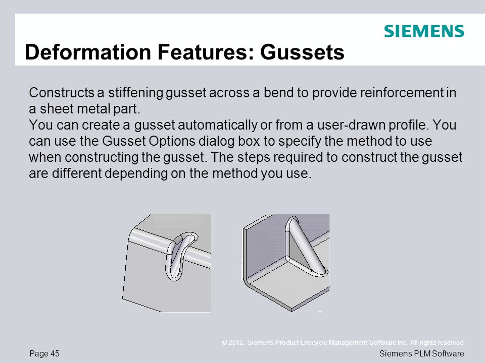
Sheet Metal Gusset Design Guidelines - DesaignHandbags
Sheet Metal Gusset – SheetMetal.Me
Sheet Metal Gusset Feature | DesignPoint Blog
Design Guidelines – SheetMetal.Me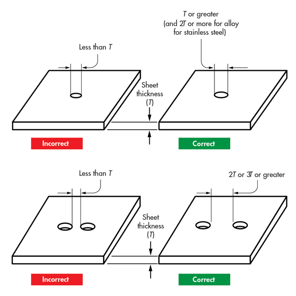
Following DFM Guidelines for Working with Sheet Metal | Machine Design
Sheet Metal Gusset Feature | DesignPoint Blog
2018 SOLIDWORKS Help - Sheet Metal Gusset PropertyManager
Design For Manufacturability – Sheet Metal Guidelines
7 Must-Follow Sheet Metal Design Guidelines to Strengthen your Design | DFMPro Blog
Sheet metal unrolling - Grasshopper - McNeel Forum
Mechanical Design Tutorial: SHEETMETAL DESIGN
Hem Feature Design Guidelines in sheet metal design | Sheet metal drawing, Metal sheet design, Sheet metal
Developing design guidelines for load carrying sheet metal components with regards to manufacturing method
SHEET METAL DESIGN HANDBOOK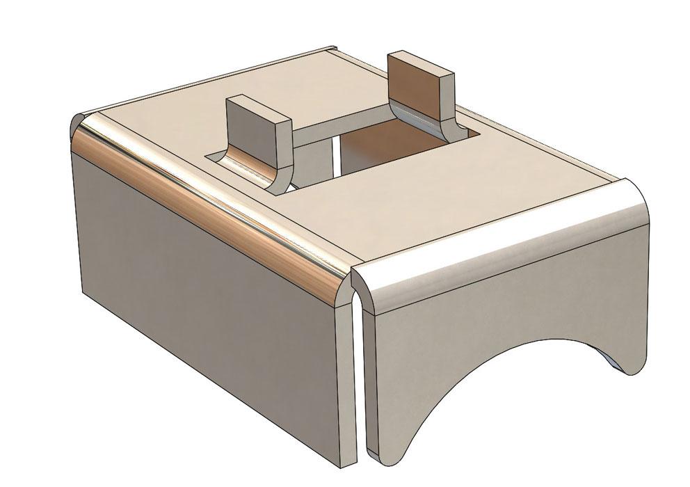
What sheet metal shops wish you knew: Reasonable tolerances, grain direction, and the base flange
Following DFM Guidelines for Working with Sheet Metal | Machine Design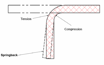
Die Basics 101: Bending methods--Wipe, coin relief, pivot, V bending
Design For Manufacturability – Sheet Metal Guidelines
Untitled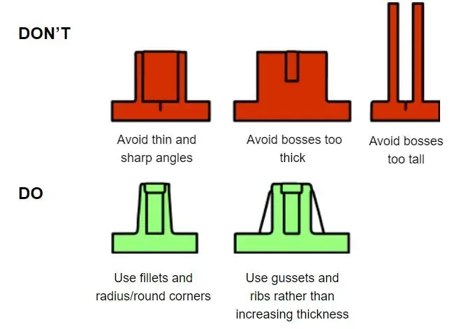
Using Simple Structures and Hacks To Design More Durable Injection Molded Parts-Design Tips-First Part China Limited
Sheet metal strength simulation with gusset and without gusset - YouTube
Injection Moulding Design Guide - Geomiq
Mechanical Design Tutorial: SHEETMETAL DESIGN
7 Ways to Improve Sheet Metal Parts
Solid Edge sheet metal design
Pin on SolidWorks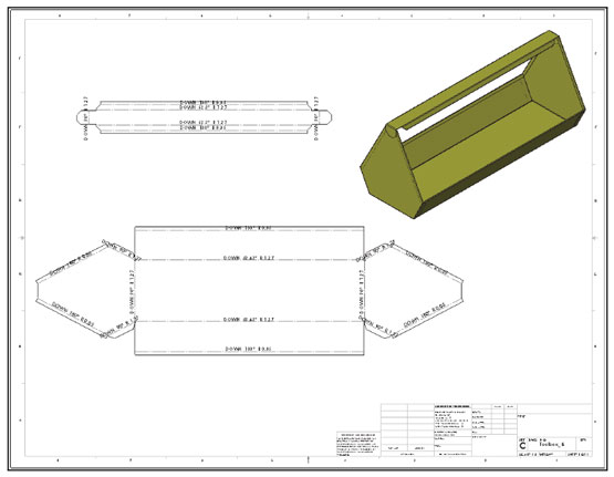
The Ultimate Guide to SOLIDWORKS Training - Sheet Metal
2015 SOLIDWORKS Help - Sheet Metal Gusset PropertyManager
Sheet Metal Design Handbook | Sheet Metal Design Guidelines | Astcad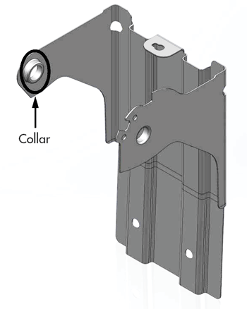
Following DFM Guidelines for Working with Sheet Metal | Machine Design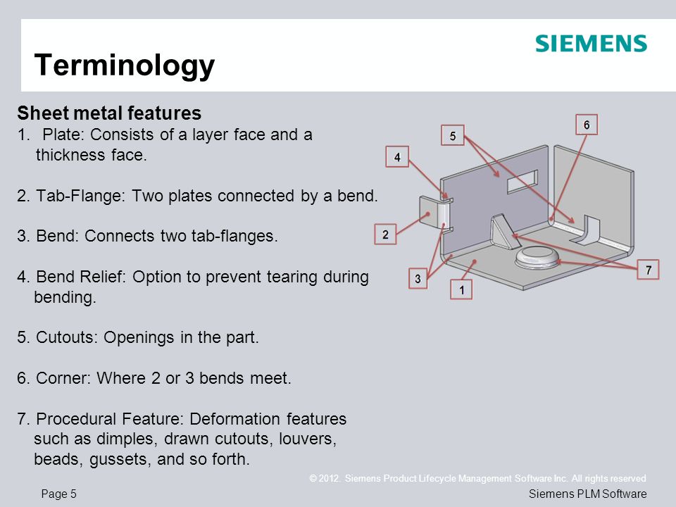
Siemens Product Lifecycle Management Software Inc. All rights reserved Siemens PLM Software Solid Edge ST5 Training Sheet Metal. - ppt download
How to Design Assemblies to Be Self-Locating and Self-Fixturing - Fictiv
Using Simple Structures and Hacks To Design More Durable Injection Molded Parts-Design Tips-First Part China Limited
Sheet Metal Designing Concept-In Detail - YouTube
Pin on Solidworks
Design Stronger Molded Parts: Ribs, Gussets, and Materials
Design For Manufacturability – Sheet Metal Guidelines
The Cardinal Rules of Designing Injection Molded Plastic Parts
 Sheet Metal Gusset Design Guidelines - DesaignHandbags


Posting Komentar untuk "sheet metal gusset design guidelines"